 |
|
 Главная
- Анатомия ножа
- Ножны
- Мастерская
- Материалы
 Процесс изготовления
- Заточка
- Темляк
- Ковка
- Дамасская сталь
- Булат
- Мокуме Гане
- Ювелирное дело
- Травление
- Химия
- Ножевой бой
- Ножевые интернет ресурсы
- Онлайн магазины
- Чертежи
- Книги
- Делаем первый нож
- Национальные ножи
- История ХО
- Нож. Общая информация.
- Knifehelp благодарит
- Последние обновления

Процесс изготовления лайнера от custombladeworks
promised before to make a tutorial about one of my folding knives.During the making of my backup 2 I took a lot of pictures of each step.Now I have collected the best pictures in order to give it a try.This tutorial only describes one of the methods I am using, for each knife I try other techniques and tools to increase the quality.This tutorial is a good example how to make a folding knife with the minimum machines and tools.Maybe good for people who wants to start with knifemaking.Other processes like sandblasting, encarving, etching, anodizing,… are not included into this tutorial.After all there goes a lot of work into knifemaking.After this tutorial you will imagin how many.
How to start ?
Consider what you want to make.There are a lot of knife styles and I suggest to one of your favourite designs.This encourage yourselves during difficult moments in the proces.Maybe you can dissassamble a cheaper folding knife and copy this on paper.A good design is the most important.Everything has to fit and work properly.Dont try to design something new to start .Save it for the next knives.
What do you need ?
Of course a good place to work because you are going to make noise, dust .You need place for some machines.Also the whole proces can’t be done within a day so you need place for everything.
About your tools and materials ?
Try to locate some typical knifemaking materials to save time.It’s not the ideal way to start making your own screws, handlematerial so buy them on the internet.Because a lot of handwork is envolved there is need to make some jiggs and fixtures.I am making those from wood in order to get correct results during milling, grinding.I will explane this later.
About safety ?
Don’t think, it won’t happen to me!Always use your safetyglasses, gloves and dustmask.Keep your work area clean and give everything a place.Stupid things surely happen in a messy workplace.However most of the work is done by hand there always a reason to get into machinery.I suggest : follow the manual instructions of your machines and think before, not after.
What knifeparts do you need ?
- heat threatable steel for the blade ( 1 piece about 30 to 90mm,3.2mm thick)
- heat threatable steel for the frame ( 2 pieces of 30 to 100 mm,2.5mm thick)
- glassfiber laminate for the handle ( 2 pieces of 40 to 100 mm,3mm thick)
- 1 stainless steel pivot en matching screw ( shaft dia 5.5 x 8mm long, head 8mm)
- 4 stainless steel screws for handle (head dia 4.7mm,thread min 5mm long)
- 2 stainless steel screws for clip ( head dia 5mm,thread min 5mm long)
- 1 clip ( I have used 6al4v titanium)
- 2 washers ( inner dia 4.5mm, outer dia 12mm)
- 1 piece G10 for the spacer ( 4mm thick,about 20 to 75 mm)
- 1 stainless detent ball ( 1.56 mm is common size)
- 1 thumbstud (I have used one with thread dia 3.2mm)
- 2 smaller pivots for handle screws ( dia about 4.7mm,min 7mm long)
- 1 stoppin (used piece of drillbit dia 3.2mm)
What tools do you need ?
- bimetal iron saw ( I prefer 24 teeth/inch for steel and titanium)
- file for course profiling materials ( I prefer Valorbe)
- counterbore for pivot ( pilot 3.2mm,counter 7.9mm)
- counterbore for handle screws ( pilot 2.5mm,counterbore 5.2mm)
- drillbit for pivot : 5.5mm en 3.2mm
- drillbitt for handlescrews 2.5mm en 3 mm
- drillbit for handle pivots : 4.7mm
- drillbit for detent ball : 1.5 mm
- drillbit for thumstud : 3.2mm
- drillbit for stoppin : 3.15mm
- tapping bits for clip ( size M3 )
- cutoff discs ( type dremel, 0.6mm thick,dia 20mm or 25mm)
- small file for stoppin area in frameparts ( type used to sharp chainsaw, modified)
- small grinding wheels from dremel
- grinding discs for shaping ( dia 25 en 60mm)
- grinding belts P60-P100-P180
- clamps ( use different sizes, look at the pics in case of doubt)
What machines do you need ?
- drillpress ( speed 550-2900 tpm)
- beltgrinder ( I have used with 0.75 Hp
- dremel with milling fixture
What products do you also need ?
- abrasive paper for polishing and removing burrs (P240 to P1200)
- oil to cool during milling,drills and tapping
Other useful things ?
- a drilling fixture
- a fixture to grind the bevels of your blade
- a wouden base to mill the lock with your dremel
- something to measure the angle of the bladelock
- magnifier
- a grinding jig to work the lock correctly
- magnet to hold the blade during sanding
- scriber for steel


The blade of the knife has a linerlock.If you know how to manage this safety system I advice you to look after a good book.Probably “the anatomy of the tactical folding knife” by Bob Terzuola is the best to start.You really need background about geometry of the linerlock.


THE PARTS YOU HAVE TO MAKE

THE MAKING OF THE PATTERN AND WOODEN JIG
Make a good pattern of your design on paper and make it look like a x-ray.Draw it on actual size.If you doubt about the size lay a favourite folding knife against it.Once convinced draw your details.Make a second pattern of the blade on transparant paper en put it above your first pattern.It’s a good way to control the right sizes and geometry.Finish your definitive pattern.Put everything on paper : spacer, pivot-location, location of the holes, the lock.Make at least 3 copies of your pattern Cut out one pattern for the blade and one for the handle.Glue it on a piece of wood about 6 mm thick.Saw the pattern around the contours.Drill the pivot with a 5.5mm drill on both patterns.Saw your pattern from the wood as close as possible to the marked lines.


Drill the pivot with a 5.5mm drill on both blade and handle jigs


Now it time for shaping the wooden knife with the beltgrinder and dremel.Use the edge of the belt for rough shaping and the dremel for the smaller finger contours.Fix the mill fixture on the dremel and keep it upsidedown for easy working.

Take your stainless steel pivot and fit both wooden parts together.Now you can feel your “knife” for the first time.If needed you can already make some corrections to the design until it fits allrightIf the design looks good you can finish your wooden jig.Drill your holes for the handle screws with a 4.7mm drill.Now you can use it as a guide to scratch right design on the blade steel and handle materials.

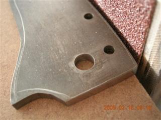
THE BLADE
Locate your wooden blade jig on the piece of steel and mark the pivot area with your scriber.Fix the steel and blade jig in the drilling fixture and drill your pivot through the jig with a 5.5mm drill.Place your pivotpin in the hole and scratch the design on the steel by following the countours of the blade jig.Here you can also colour the steel before to get more visible marks.Drill the hole for the stoppin with a 3.15mm drill.Put a piece of 3.15mm drill (2-3cm)through the blade jig into the steel to stabilize.Drill a hole for the thumbstud with a 3.2mm drill.Now you can release everything from the drilling fixture.


Cut away the excess steel close to the marks with a bimetal saw.I suggest a 24th/inch metalsaw.Don’t touch the lines.Grind closer to the lines with your beltgrinder by using course belts.Smaller curves can be done with the edge of the belt.Course grit about P60 until P100.Use your abrasive discs in the drillpress to finish the curves and get a nice grind.Your blade should be ready for grinding but I always start with the handlemaking to get it all assembled already.A full assembled knife ( even without bevels on the blade) enables me to check the dimensions and fit of all parts.Grinding the blade’s bevel comes later in the project.


THE HANDLE FRAME
Fix your frame-steel in the drilling fixture under the handle jigg and locate the pivot again.Mark the pivot with the scriber.Remove the jigg and drill the 5.5mm pivot hole in both frame pieces.Now you can push your pivotpin through the handle jig into the steel.Locate and fix the jig and start drilling the 4.7mm holes for the handle bushing.After drilling put your handle pivots into the frame through the jigg to hold in all in place.Mark the contours of the handle jig on the steel with your scriber.Here you can also colour the steel for better visible marks.You can release the parts from the drilling fixture.


Cut out your handleframes with the bimetal saw close to the marks.Again use your beltgrinder to grind away the excess steel.Here you can also use your drillpress with abrasive discs to get a nice and close grind.Remove burrs from drilling with abrasive paper.Use some magnets for easier grip during sanding.


THE G10 HANDLE SPACER
It’s not urgent but I suggest to make that G10 spacer before drilling the handlescales because it gives your extra stability during drillwork.Fix your spacer material and 1 handleframe in the drillingficture and drill 4.7mm holes.After drilling remove it al from the fixture and assemble the spacer with the handlepivot.Scribe to contours of the frame on the material.Also assemble your blade with the pivot and simulate a closed blade.Scribe the edge of the blade on the material.This will be the inner side of the spacer close to the edge . Now you can push your handlepivots through the spacermaterial for easier working during fine grinding close to the scribed marks.


Now you can fit the handlepivots through the spacermaterial for easier sawing and grinding.Use a small clamp too.Grind close to the scribed lines and check regular the fit by mounting the blade and closing it.Leave 0.5/1mm extra space between the blade edge and spacer.


THE G10 HANDLE SCALES Now we have made finish the frames and start with the G10 handle scales.Locate the one handleframe on the G10 piece and mark the pivot on the G10 with your sriber.Drill a hole for the pivot.Here we are using a counterbore 3.2/7.9mm so first we drill a pilothole about 3mm.


Drill a recess about 1 mm depth for the 8mm pivothead.Drill the 3.2mm hole with a 5.5mm drill for the pivot shaft.If needed ream the hole for tight fit with a reamer or rolled up piece of fine sanding paper ex.P 400.Do the same for the second handlescale.


Fix your handlescales and one framepiece in the drillingfixture.Use your pivotpins and spacer to stablize all parts during drilling.Drill your handlescrews holes through the handlepivots into the G10 by using a 2.5mm drill.Don’t damage the thread inside the handlepivots.The holes in the G10 should now be correctly centered to the holes in the handleframe.Start recessing screwholes in the handlescales with your smallest counterbore 2.2/5.2mm.Check with the screws for depth.


Shape your handlescales into a oval shape by slack beltgrinding or sand it on a jig like if done.With the jig you can easily sand both scales in the same shape.It’s also a cleaner way than grinding it with the beltgrinder.The jig is been made by myself from wood and the hollow shape is based on a circle about 300mm.


Assemble your left handlescale between the frameparts and grind away close to the contours with your beltsander an dremel.With the G10 between the frameparts is easy to grind it exactly the same size.Do this also for the opposite handlescale.


Finish the countours with fine abrasive paper on your grinding discs in the drillpress.At most grinding jobs I am using the wooden handle jig as support.Aways stabilize the parts by using your pivotpin and screws.Too wide screwheads can be sand with the drillpress against abrasive paper glued on a wooden piece.Too long screws can be shortened if fixed in a piece of wood.Sometimes by recessing the wood with the counterbore you can adjust the depth of the screwhead in the wood in order to grind more or less away from the screw.


The handlepivots can easily being shortened with the dremelfixture.Make a wooden base for milling with your dremel, drill some holes of matching size for the handlepivot ( in this case 4.7mm) and fix it underneath the base.Cutoff the excess steel and flatten the pivots afterwards against a course and fine abrasive paper under your drillpress.The handlepivots should be 6.9mm long.


THE ROTATING STOPPINMake a 6.9mm long stoppin from a 3.2mm drill .Shorten the drillbit following above explained method.Be sure that the stoppin fits tight in the blade.Fix your blade and handleframes in the drilling fixture.Stablize with the handlescrews and pivot.Locate the blade in the correct open position to the handle and drill a 3.2 mm hole through the blade into the frameparts.Loosen the parts, turn the blade to the correct closed position in the handle and again drill a hole through the blade into the frameparts.These two holes has to be correctly made because it has directly influenze to the look of the blade in both positions.Turn the blade to drill every next hole.Drill 1 framepart at a time.Fix the undrilled framepart underneath and use the drilled part as a guide to drill the other holes.Drill all holes close to each other.


We are using this methode due the lack of a mill.File the holes away in one direction with a narrow file or a modified sharpning file.


Finish the slots with sandpaper.For this job I have made a special jig from a metal tube.


The stoppin must easily move within the frameparts so check it by assembling all parts.Assemble your blade in the frameparts with the pivot and screws and the washers ! Check the open and closed positon of the blade in the handle.File-sand away where needed without touching the ends of the slots.The stoppin must always touch the end of the slots of both frameparts.The washers can be made by punching them from a sheet of 0.5mm thick teflon.Here I have used 5.5mm for the inner size and 12mm for the outer size.More than 12mm should touch the stoppin.Be aware of it.


Assemble all your parts and figure out the ergonomics.Does it fit comfortable in your hands ? Can you easily open the blade with the thumstuds ? Maybe here is the moment for some corrections of the contours.Once fully assembled is also easier to check the area between blade and spacer.Try to move a narrow piece of paper between it.If you cant move it you must grind the blade-edge a bit more away.The blade may never touch the spacer ! Try it with paper thickness 0.5 to 1mm.


GRINDING THE BLADE
Now it’s time for grinding the bevels on each side of the blade . On goal is a thin edge about 0.5mm . The height of the bevel is less important an rather a case of personal interest . It’s more important to grind them on each side the same . The get it right we have to mark the edge and the bevels on the blade . First of all , colour the blade in a blue color . I have used different paint markers . If you paint the blade while it’s warm ( ex.after finishing with your sanding disc under the drillpress) the paints won’t loose so easily . Find some flat, stable underground to work while scribing the grinding lines . A marble or granite window sill could be a solution . Here you’ve got a lot of light and a stable underground . Clamp the blade . Our goal is to scribe two parallel lines at the center of the blade . Lay your scriber flat on the sill and scribe a line on the full edge of the blade . Loosen and turn over the blade . Now scribe your second line . If done correctly the two lines should be parallel and close . About 0.4mm between the lines is acceptabel for course grinding . You can manage this by adding some paper under the blade in order to get the scribers point closer to the edge . Of course it’s also depending on the type of scriber.Place your blade vertical and scribe the marks for the height of the bevels.For this kind of blade about 12 tot 14 mm height.


Grinding the steel is matter of exercise . If you haven’t done it before try it before with a second piece of steel . Grinding directly the belt without support is almost impossible . I have made some wooden base on my beltgrinder for stability . It also gives the advantage of easier changing the angle of grinding with a fixture . I start grinding with a course belt at one side a mostly turn of the blade after finishing the half of the work.Grind between the marks on the edge and the scribed lines at the side of the blade . With a fixure you can easily change the angle a grind it flat.I grind from the ricasso to the point . Always move the blade when you touches the belt . I also use some piece of steel to avoid mistakes and grinding to wide . It’s gives a nice ricasso . The third picture illustrates my new grinding fixture.


THE LOCK
Assemble the blade to the framepart you want to use as locking liner and improvise the lock wit a ruler . Scribe your grinding lines , they should be rectangular to the horizontal spring .Now it’s time for the lock of the blade . Fix the blade on the grinding machine , take care of some support and grind the blade lock a an angle about 8°.That’s what I have used for this knife but you can try other angels of course . Somewhere betwen 7° and 9° is correct but most important is to get it really flat . If not it could result in a bad lockup due the wrong contact-area of the spring to the blade . The best lockup happens at the lowest part of the blade . Stabilize your grinding work and use some straight piece of wood or metal to guide the blade to the grinding belt . Grind little at a time a check the angle .


Once done finish the blade’s lock with fine sanding paper on a flat and hard underground . Also here a window sill could help . I advice you to check the lock to the sill by using the incoming light from the window . Remove small burrs !


Assemble the blade to the framepart you want to use as the locking liner . Mark the place of the blade’s lock and scribe a horizontal line where you are going to cut the lock . A metal ruler helps to define the right length . The spring here is about 50mm long . Shorter spring won’t work easily with 1.5mm thick titanium . Prepare your milling base for the dremel . That base is nothing more than a piece of work with a hole about 50 to 100 mm.


Disassamble the parts and locate the framepart underneath the base by using a wooden block of matching size . Use small clamps to fix the framepart . Be sure to fix the scribed line parallel to the base , use something to check the setup like such a geometric measuring jig . Cut at firts the long part of the lock and afterwards the short piece with a fine 0.6 mm cutoff wheel from dremel . For this job you’ll need different cutoff wheels and a slow speed about 5 to 10.000 tpm . Some grooves in the wood from prevouis milling jobs can help for a correct setup . Leave enough space when milling the short cut-out. The finer work comes has to be done with the beltmachine .


Drill a wole for the detent ball . Assemble the blade and milled liner together with your pivot and mark the rotation of the blade on the steel . This curves shows the covered area on the spring when the blade moves during opening and closin . Here in this area you have to drill a 1.5mm hole for the 1.56mm detent ball .Remove all burrs after drilling .


Make a copie of the pivot and detent holes on a extra small piece of steel . You’ll need this for correct drilling of the detent .First drill a 5.5mm hole in the center of the steel . Fix the steel under the milled liner ,stabilze with the pivot and drill a 1.5mm hole throught the liner in the steel .Now you have some guid for final drilling of the detent into the blade . You only need the right distance of both holes . At the right picture you can see 3 holes but that’s only because I have used the guide for different blades . Further explanation comes later .


FITTING OF THE LOCK
Remove all parts from the milling base and check the vertical scribed line . If needed assemble all parts again and scribe a new line against the blade’s lock . Now where going to sand the steel away close to the scribed line . For this job we need some fixture . I made some wooden fixture similar to the one described in the book used by B.Terzuola . It’s no more than a wooden bar with some drilled holes and screws at the right place . Drille a hole about the same size of your pivot at the edge of your wooden bar . Clamp the milled liner on the wooden bar with your pivot and adjust the spring lock perpendicular to the platen of your beltgrinder . Mark the contours of the liner on the wood and drill holes through the liner into the wood of matching size . Here about 4.7mm . This holes are needed for correct setup of the liner after each checkup of the lock . The drillbits ( or you can use the handle pivots fo course ) enables to setup your liner into the same angle and location to the platen . Make a screw at the bottom of your wooden fixture to enable adjustment of the horizontal angle . That’s important because you need to sand the material parallel to the scribed lines . Place a second screw at the side of the fixture to push your spring away from the fixture . Otherwise you can’t reach the spring . Put some tape where the belt is touching the liner to avoid scratching the steel . Now setup your wooden guide at correct angle and clamp it on the wooden base . Here you can angle the spring lock to the wanted angle . If you are going for a positive lock adjust it at the same angle of the blade’s lock . I suggest to angle it at 90° because the bending of the spring also changes the contact of blade and spring .


Sand away little by little until reaching the vertical scribed line and disassemble the liner from the fixture for a first check of the lock . Always remove burrs from the locks face to get a correct sight on the lock . Check it at daylight . Fix your liner to the fixture again to sand more away until the spring lock can move beyond the blade’s lock . Here comes the tricky part so I advice you to color the blade’s lock with the same blue paint like used before . In most cases it’s better to grind your spring lock at a light angle an not parallell to the blade’s lock ,this in order to secure contact of the spring a the lowest part of blade . I advice you to bent the lock a few millimeters and assemble all parts of the knife to check the lockup . Again use tape on the liner and your pliers to avoid scratching the steel .Try to bent the liner in a progressive way and avoid bending it at one area . In this way the spring will work without pushing too hard against the blade . You need some upgoing curve and probably you have to re-bent the spring until it locks the blade in the opened position . If it rocks up or down your contact point is what it should be . However I suggest to try several curve in the spring rather than grinding too much away from the spring lock . Once you removed steel you can’t go back or you have to deform the spring lock by punching it on a hard surface with a heavy hammer . This part is also mentioned in the book but I haven’t tried this before . I was lucky .


Now it time to press the detent ball into the 1.5mm hole close to the spring lock . Use some tape to hold the ball into the hole and press it about 1 mm deep . Use a punch or bench-vise to press it in the spring . Hammering the ball to the desired depth works better when using a 0.5 mm washer around the slightly set detent ball . The washer will prevent from hammering too deep . When pressing the ball into the steel with your bench-vise there’s a big change of deforming the vise , to prevent a small hole into your contact platen I advice to use a small piece of steel as support .


When the detent ball is set is time to drill the detent hole in the blade . Color the blade with your blue paint and assemble the knife completely . Open the blade several times , don’t push when closing . Disassemble the open blade and not while closed . Now there is a narrow track of the ball movement around the pivot area . At the end of the track you’ll need to drill a 0.5mm hole . This is a very important and tricky part of the knife . There is a big change of drilling at the wrong location : too far beyond the track ( here you need to get the blade in a more closed positon to solve ), before the track-end ( here you need a bigger detent ball and start over again , I was lucky again ) or out of line ( that’s worse and mostly difficult to solve ). It can be simply done correctly by using your small drilling guide made before . You remember that small piece of metal ? Fix your blade and this guide with the pivot in your drilling fixture . Locate the 1.5mm hole of the guide directly above the end of the track but turn it 0.5mm more . Your track-end should be visible but close to the inside of the 1.5mm hole . Check it with your magnifier . Drill with your carbide 1.5 mm through the guide . Stop drilling after 0.5mm . When done all right you should now have a correct lockup of the closed blade without play .


Close-up of the lock

THE BELT CLIPIT
For this knife I have used a titanium belt clipit and had to drill small holes by myself . I planned to use M3 threated screw so first I drill 2 2.5mm holes in the titanium clipit . It’s a small piece and not easy to clamp while drilling so try get it stable in the drilling fixture . Color the framepart and locate the place where you want that clipit . Clamp everything and drill a first 2.5mm hole through the clipit into that framepart . Remove it from the drilling fixture and tap a M3 thread in the first hole . Enlarge that 2.5 mm hole in the clipit with a 2.9 or 3mm drill for the screw . Screw the clipit on your framepart before and drill the other 2.5 mm hole for the second screw . Again tap with a M3 thread tapping set . Also drill you second 2.5 mm hole in the clipit to 2.9-3 mm and apply your second screw . In the right picture you can see that the clipit is covering the pivot area . Here I have planned to fit the pivot and clipit close together to prevent the turning of the pivot while opening or closing the blade .


Assemble the G10 handlepart underneath this framepartin the drilling fixture and drill 2 holes about 2.5 mm through the the framepart into the G1O . Be sure to aline all parts correctly by using all of your pivots you’ve made . These holes has to be at the right place . Clamp the G1O handleparts and this framepart together and tap the thread from the framepart into the G1O . The thread has to be continuous so start from the framepart . Be sure to clamp everything very close . Assemble the screw again , mark where you need to shorten them .


Some titanium and some steel of the pivot-head has to be removed . Remove some titanium close to the scribed line and shorten your pivot-head on a piece of abrasive paper . Assemble the clipit with your screws an mark the area you want to grind the pivot head . Carefully grind the pivot until it fit . Grinding that pivot-head can easily can been done with a small piece of wood as aid . Drill a 5.5 hole close to the edge of the wood and press the pivot into it . Now you can hold the pivot without dropping or burning yourselves .


FINISHING THE KNIFE
Now you need to finish the blade by removing all scratches with abrasive paper . I mostly start with P180 but that’s depending on the grain size of your belt. Followed by P240-400-600-800-1000-1200 . Most of the big scrathes has to be removed with a used belt or some new around P180 . While sanding the blade I change of grain size when all previous coarser scratches are removed . With every new grain size I also sand into another direction . Important also is to clean all parts before using a finer grit .During sanding I use some magnet to hold them easier . Sharpning is done with a fine or used belt . For sharping or sanding I advice you to look after other tutorials on the net .


Also take care of the G1O handleparts to smooth the edges with some abrasive paper . After a first tryout of the knife it’s possible you need to bent the spring a bit further . After use the lock will set .The knife finished
